Ball Balancing Rotary Stewart Platform
Project Summary
What?
The aim of this project was to design and build a 6-degree-of-freedom rotary Stewart Platform capable of balancing a ball. The idea was to keep the ball at the platform's center by controlling the platform's pose (position and orientation) based on the position of the ball relative to the platform's center.
How?
-
Designed a 3D model of the rotary Stewart platform using Autodesk Fusion 360, and 3D printed most of the parts
-
Implemented machine vision using OpenCV to track the position of the ball, as well as the centre of the platform
-
Derived the inverse kinematics of the Stewart platform via transformation matrices, and then related link lengths to servo angles
-
Implemented a PID controller that takes the distance of the ball to the platform's centre as the system's error, and minimizes that error by changing the pose of the platform
-
Utilized Ziegler-Nichols method to tune the PID controller
-
Developed C++ code for an Arduino to control the servo angles based on the PID controller's output using the inverse kinematics equations
Outcomes
The rotary Stewart Platform successfully balanced the ball at the centre. The controller ended up being a PD controller because the proportional term controls how much the platform tilts, and the D term minimizes the velocity of the ball and brings it to zero. The integral term tracks the accumulated error over time which serves no real purpose in this case.


Control Algorithm

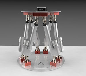
What is a Rotary Stewart Platform?
A Stewart platform is a parallel link manipulator that uses linear actuators to control the length of each link connected to a platform, which in turn changes the pose of the platform. On the other hand, a rotary Stewart Platform uses rotary actuators to control the pose of the platform based on the angle of rotation. The images below show both types.
Stewart Platform

Rotary Stewart Platform
Inverse Kinematics
The first step to designing a Stewart platform is to relate the pose (position and orientation) of the platform to the length of each link. The aim is to be able to calculate the length of each link given a desired platform pose. This is referred to as inverse kinematics. The image below shows vectors relating the base frame to the platform frame.

-
The vector P describes the x,y,z position of the centre of the platform
-
Vector d represents the leg length
-
a is a Vector from the centre of the base to each leg anchor on the base
-
b is a vector from the centre of the platform to each leg anchor on the platform
The platform position P can be written as a sum of vectors a, d, and b. Since the orientation of the platform changes, the vector b must be rotated by multiplying it by an equivalent rotation matrix. The vector sum can be seen below:
Rxyz represents the equiivalent roll, pitch, and yaw rotation matrix representation. The above summation can then be rearranged to solve for the leg lengths:
The vectors a and b can be represented using the angle of each leg anchor on the base and platform relative to the horizontal axis:

Hence, the leg length vector can be calculated given a desired platform x,y,z position and orientation as follows:

The length of each leg can be calculated as follows:

Now that the inverse kinematics for the standard Stewart Platform has been derived, the desired platform pose can be achieved by changing the leg lengths. Since rotary servos are used to control the platform, the leg length must be related to a servo rotation angle. This servo angle can be calculated from the leg lengths using geometry. The procedure for deriving this relation is algebraically arduous, so the full derivation can be seen in the calculations PDF. Hence, the servo angle is obtained as:


-
di is the leg length of the ith leg
-
k is the length of the servo arm
-
L is the length of the rod connecting the servo to the platform
Computer Vision Model
Object detection is a branch of computer vision that is comprised of 3 main processes:
1). Object Recognition
2). Object Classification
3). Object localization (bounding box)
Platform Control
In order to get the ball to the centre of the platform, the platform must be rotated about an axis that is perpendicular to a line from the centre of the ball to the platform's centre. Given that the x,y position of the ball is known, a unit vector representing the required axis of rotation can be mathematically derived. The image below shows an orange ball on the blue platform.

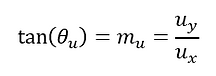
The points xb and yb describe the position of the ball relative to the centre of the platform. The vector u represents the required axis of rotation for the ball to move towards the centre and is perpendicular to the (black) line from the centre of the ball to the platform's centre. The equation of the black line is:

Since the required axis of rotation is perpendicular to the black line, the product of the gradients is equal to -1:
Hence, the gradient of the required axis or rotation can be solved for:

The vector representation of the required rotation axis is:

The angle of the axis relative to the platform's x-axis can be described in terms of the rotation axis vector components and its gradient:
We can represent the required rotation axis as a unit vector with a magnitude of 1 and in terms of the balls position using the following two expressions:


Hence the vector components ux and uy can be solved for, providing the rotation vector as:

Quaternion Representation
Quaternions are 4-dimensional mathematical objects that can be used to represent rotations. They are closely related to the axis-angle representation. The structure of a quaternion is as follows:
The unit vector representing the required rotation axis can be used to obtain a quaternion to describe the platform rotation:

Theta is half the required angle of rotation. The quaternion can be converted to an equivalent rotation matrix :

In order to control the platform with a single rotation axis, the above rotation matrix can be used in the inverse kinematics instead of the roll, pitch and yaw matrix representation:

Algorithm Summary
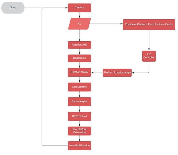
The algorithm for balancing the platform is described by the flow chart below.
Two PID Approach
Using the quaternion approach requires the rotation axis of the platform to be defined but in turn only needs one controller to be used. An alternative approach using two PID controllers to minimize the error in the ball's x position and y position independently. This approach takes the x-component of the ball's position and reduces the error to zero, and does the same to the y-component.
Project Progress Videos


