Cycloidal Reduction Gearbox
Project Summary
What?
The aim of this project was to design and build a 15:1 cycloidal reduction gearbox for a robot arm. The cycloidal drive consists of 4 main components as follows:
1) Gearbox Housing: houses all the components of the gearbox.
2) Eccentric Shaft: converts the rotary input motion to an eccentric motion needed to drive the cycloidal disk.
3). Cycloidal disk: transmits the eccentric motion to rotary motion with increased torque and reduced speed.
4) Rollers: provide a low-friction surface for the cycloid to roll about.
5) Output Shaft: transmits the increased torque to the output.
One of the advantages of using a cycloidal gearbox over other types (such as planetary gearsets) is that there is virtually no backlash. Additionally, the cycloidal disk is constantly in contact with multiple rollers, so stresses are not concentrated on a singular tooth profile.
How?
-
Designed a 3D model of the gearbox using Autodesk Fusion 360, and 3D printed most of the parts
-
Designed the Eccentric shaft in sections and added screws for extra strength.
-
Sourced all bearings and non-3D printed components
-
Performed calculations for the reduction ratio of a cycloidal gearbox
-
Two cycloidal discs, 180 degrees out of phase, were used in this design to reduce vibration effects
Outcomes
The cycloidal gearbox operated smoothly and had negligible backlash. The use of bearings for the rollers is a good idea for friction reduction; however, this increases the overall cost of the gearbox. In the next iteration, metal bushings will be used instead. The efficiency of the gearbox was measured to be about 62%. This is likely due to the use of 3D-printed components.
Cycloidal Disk

Rollers and Housing

Gearbox Assembly

Eccentric Shaft

Output Rollers and Shaft

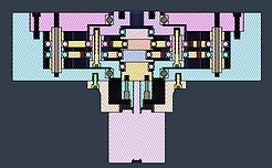
Section View

What is a Cycloidal Gearbox?
A cycloidal gearbox is a type of gearbox that utilises a gear with a tooth profile that is a cycloid. From mathematics, a cycloid is the path that a point on a circle traces when it rolls along a surface. Hence, the tooth profile of a cycloidal gear is the cycloid that forms while a smaller circle rolls along the circumference of a larger one.

Cycloidal Gear
The following parametric equations describe the shape of the cycloidal gear:
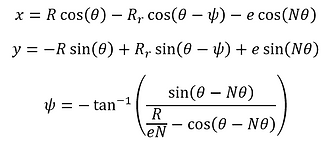
R is the radius of the circle that the rollers lie on
R
r
is the radius of the rollers
e is the eccentricity of the eccentric shaft
N is the number of rollers
The gear ratio of a cycloidal drive is defined as:
r is the gear ratio
N
c
is the number of lobes on the cycloidal gear
For a 15:1 reduction, the chosen arrangement for the design is as follows: