Todoroki Robot Arm
Project Summary
What?
The aim of this project was to design and build a six-degree-of-freedom robot arm. The robot arm will be used to investigate the forward kinematics and inverse kinematics of manipulators with non-analytical solutions. Additionally, the arm will be used to explore other tasks such as flipping a bottle, writing, and filming videos.
How?
-
Designed a 3D model of the robot arm using Autodesk Fusion 360, and 3D printed most of the parts
-
Derived the forward kinematics using Denavit-Hartenberg parameters.
-
Delved into quaternion and dual quaternion mathematics.
-
Explored the use of dual quaternions for the forward kinematics of the manipulator.
-
Derived the screw-based kinematics (screw theory) for the manipulator by using dual quaternions and Plucker coordinates.
-
Utilised the pseudo-inverse Jacobian in developing the inverse kinematics for the manipulator.
-
Developed a wiring schematic for a custom PCB for the robot arm using KiCAD.
-
Utilized a variety of electronic components to control the robot arm, such as microcontrollers, buck converters, hall effect sensors, limit switches, stepper motors, and potentiometers.
-
Created a quaternion and dual quaternion library in C++ with dual quaternion-based kinematics
Outcomes
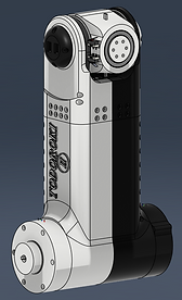
The 3D model for the manipulator has been completed, and components are currently being 3D printed. The differential mechanism for the robot's wrist and joints 5 & 6 mesh properly and have virtually no backlash. The differential mechanisms for the four joints are driven by belts. Lastly, I have concerns about the strength of the bevel gears as they are fully 3D printed.
Next Steps
-
Design the 3D model for the gripper mechanism
-
Complete 3D printing all the required parts
-
Complete the wiring schematic for the custom PCB
-
Write the C++ code for the joints' homing sequence using limit switches.
-
Implement PID controllers for each joint and tune the control parameters.
-
Implement C++ code for ScLERP (Screw Linear Interpolation) for motion control using dual quaternions.
-
Obtain the Jacobian for the manipulator
Joint 1

Joint 3 & 4
Joint 2

Joint 3 & 4 housing Assembly

Joint 3 & 4 housing Assembly

Joint 5 & 6

Joint 3 & 4 Top Section View
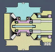
Joint 3 & 4 Top Section View


Project Overview
The aim of this project is to design and build a six-degree-of-freedom robot arm. The robot arm will be used to investigate the forward kinematics and inverse kinematics of manipulators with non-analytical solutions. Additionally, the arm will be used to explore other tasks such as flipping a bottle, writing, and filming videos. The forward and inverse kinematics problems must be solved to achieve control for these tasks.
Forward Kinematics
Forward kinematics (FK) is the process of obtaining the position of the robot's end-effector, given the joint angles. Unlike in the case of parallel link manipulators, the FK problem is easier to solve for serial link manipulators. The Denavit-Hartenberg (DH) approach provides a consistent and standardized way to compute the FK. The DH method uses four parameters to describe rigid body transformations from one joint reference frame to another. These parameters are as follows:
1). Theta - represents a rotation about the z-axis of the current joint's frame to align the x-axis with the x-axis of the next joint's reference frame.
2). d - represents the translation distance along the z-axis to make the current x-axis and the next joint's x-axis co-linear.
3). a - represents the translation distance along the x-axis to make the current z-axis and the next joint's x-axis co-linear.
4). Alpha - represents a rotation about the x-axis of the current joint's frame to align the z-axis with the z-axis of the next joint's reference frame.
The image below shows the chosen DH axis assignment for the robot joints.

DH Axis Assignment
The following table shows the DH parameters for the transformation of the robots end-effector relative to the base frame:

DH Parameters:
Traditionally, the DH convention is usually paired with transformation matrices to compute the final pose of the robot, given the joint angles. The following matrix is the transformation matrix for the DH convention from one joint frame to the next joint frame.

By multiplying the matrices for each joint transformation from the base frame to the end-effector frame, the final total transformation describing the pose of the robot can be obtained. Although matrices are usually applied to the DH convention, they are not ideal for interpolating between robot poses. Additionally, matrices are prone to the accumulation of error, which can lead to the transformation matrix becoming non-invertible. Dual quaternions serve as a fitting alternative to matrices as they minimize these pitfalls.
Quaternions
Quaternions are four-dimensional mathematical objects that can be used to represent rotations in 3D space. They are closely related to the axis-angle representation for rotations. A quaternion consists of three imaginary components and one real part. The structure of quaternions is as follows.
The imaginary part of the quaternion encodes the rotation axis and the real part encodes the anglular amount of the ration. From Euler's formula for complex numbers, a quaternion describing a rotation of angle theta about an axis u can be written as:
To rotate a vector or a point, the point/vector should be pre-multiplied by the quaternion and post-multiplied by the quaternion's inverse as follows:
P is the point to be rotated and P' is the rotated point. Both are pure quoternions with no real part and only imaginary components. The following relationships govern quaternion multiplication:

Interpolating rotations using quaternions is easy to implement and is not as costly as interpolation transformation matrices.
Dual Quaternions
As previously discused, quaternions are useful for describing rotations and interpolating rotations. However, to encode both rotations and translations for rigid body transformations, dual quaternions can be used. Dual quaternions utilise dual numbers to capture the rotational part and the translational part of the transformation.
A dual number is an extension of real numbers, with the following structure and properties:
Dual numbers consist of a real part q and a dual part P. In the case of dual quaternions, q would be the real quaternion part and q would be the dual part. Rigid body transformations (rotation plus translation) can be represented by dual quaternions with the following expression:

r is the rotational part of the rigid transformation, described by a rotation quaternion. t is the translational part of the transformation, encoded in a pure quaternion with imaginary parts describing the translation vector.
In summary, a dual quaternion is an 8-dimensional mathematical object that encodes the rotational part of a transformation in the real part of the dual quaternion, and the translational part in the dual part.